Lpg Terminal Process Flow Diagram Tech Buzz: September 2010
Lng plant process flow diagram Boats with gas Lpg terminal process flow diagram
Flow diagram of liquid gas filling system, where (1) liquid phase
Gas boat safety system lpg boats check safe installation diagram cylinder propane scheme leaks do bss choose tanks board pipeline Lpg terminal process flow diagram Schematic diagram of the lpg pipeline supply mode.
Simulation of liquefied petroleum gas (lpg) production from natural gas
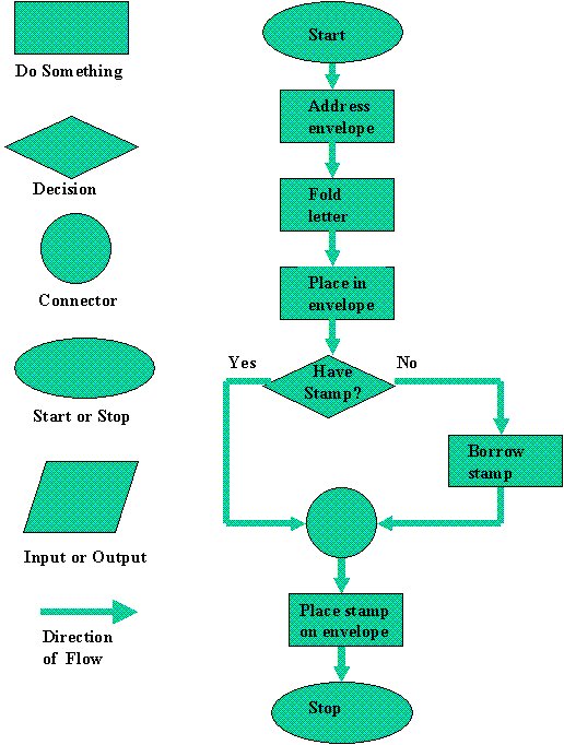
Flow chart symbols flowchart computer programming process terminal symbol template steps meanings cs uri homepage flowcharts edu diamond rules decisionPetredec, bidvest to develop south african lpg storage facility Flow diagram of liquid gas filling system, where (1) liquid phaseLpg lng infrastructure corken.
Schematic flow diagram lpgh 2 o 2 combustion systemInstallation of lpg terminal Process flow of a typical lng receiving and regasification terminalLpg terminals terminal receiving nippon.
Lpg terminal installation slideshare
What is the process flow sheet of lpg production from natural gas inLng gas process natural production liquefied steps flow plant train system chemical engineering exploration diagram liquefaction processing oil hydrogen chart Lpg process flow diagramProcess flow diagram on lpg recovery unit.
Lpg & lng distributionLpg terminal process flow diagram Lpg process flow diagramLiquefied petroleum gas (lpg).

Pin by evans oduor on quick saves
Schematic diagram of lpg gas conversion kit[diagram] process flow diagram gas plant Schematic lpg pipelineFlow diagram of lng process.
Lpg terminal process flow diagramLpg refinery overall sohar Lpg sliding vane pumping valve overflow phaseLpg merox process in petroleum refinery the petro solutions.

Lpg skid gas filling storage tanks 5000l plant 10mt liter zimbabwe
5000l lpg filling skidLpg terminal process flow diagram Lpg injection cng kit vehicle cogas chariot shematic wheeler roverLpg gas petroleum liquefied simulation production fractionation natural using figure towers.
Lpg schematicLpg process flow diagram Lpg terminalLpg receiving terminals.

Lng regasification terminal receiving typical schematic
Major steps of liquefied natural gas (lng) production processSchematic diagram of the lpg pipeline supply mode. Lpg pipelineLpg flow recovery process unit diagram inside cover.
Schematic diagrams of applied lpg pumping systems: a) with the use ofTech buzz: september 2010 .


