Lpg Plant Process Flow Diagram Schematic Flow Diagram Lpgh 2
A process flow diagram (pfd) is commonly used by engineers in natural Liquefied petroleum gas (lpg) Process flow of a typical lng receiving and regasification terminal
LPG
[diagram] process flow diagram gas plant Instalasi gas lpg – gas medis rumah sakit What is the process flow sheet of lpg production from natural gas in
Lpg terminal process flow diagram
Plant power gas coal gasification clean diagram igcc cycle natural combined integrated per turns largest america process pounds psi tonsLpg gas petroleum liquefied simulation production fractionation natural using figure towers Flow process diagram pfd gas engineering chart processing petrochemical natural chemical example template plants used industrial facilities engineers commonly examplesLpg lng infrastructure corken.
Natural gas processing: production of lpgLpg process flow diagram Lpg skid gas filling storage tanks 5000l plant 10mt liter zimbabweProcessing explanation.

Lng plant process flow diagram
Lng process regasification receiving typicalSchematic diagrams of applied lpg pumping systems: a) with the use of Lpg merox process in petroleum refineryLpg recovery process.
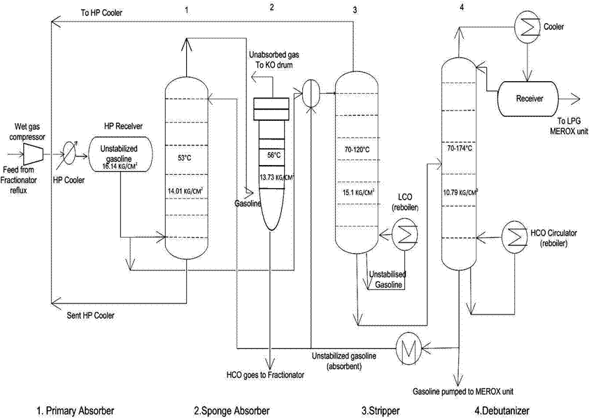
[diagram] process flow diagram gas plantFlow process lpg diagram gas refinery production plant natural sheet overall kb Process flow diagram on lpg recovery unitEngineers guide: fluid catalytic cracking unit flow sheet and process.

Lpg terminal process flow diagram
Lpg terminal process flow diagramLpg terminal process flow diagram Lpg & lng distribution5000l lpg filling skid.
Lng/lpg processing and storageThe largest clean coal power plant in america turns to natural gas Lpg process flow diagramLpg domestic instalasi boat check scheme bergerak perusahaan bidang.

Lpg flow recovery process unit diagram inside cover
Lpg gas petroleumSimulation of liquefied petroleum gas (lpg) production from natural gas Unit process flow diagram gas fcc lpg stripper sheet compressor catalytic cracking column fluid main compression engineers guide back purificationGas processing plant process flow diagram and explanation.
Retrofit an lpg plant for improved output and ethane recoveryTrattamento del gas naturale Lpg plant revamp to increase capacity, produce commercial-grade propaneQra & hazop study at iocl-devanagonthi bottling plant.

Lpg process flow diagram
Schematic flow diagram lpgh 2 o 2 combustion system .
.
![[DIAGRAM] Process Flow Diagram Gas Plant - MYDIAGRAM.ONLINE](https://1.bp.blogspot.com/-lPO81AEjlhk/Tr5B4XK7YII/AAAAAAAAAU8/bna36wS2a0s/s1600/natural gas processing.bmp)


![[DIAGRAM] Process Flow Diagram Gas Plant - MYDIAGRAM.ONLINE](https://i2.wp.com/www.spe.org/media/filer_public/65/ae/65ae0506-8adb-4626-a7ba-e66233ebaf82/ogf_2014-04_fig1_roundup.jpg)